
Shallow foundations are often placed close to slopes, excavations, road cuts, quay walls, or terrain breaks. In these situations, the bearing capacity can be significantly lower than the value calculated for the same foundation on flat terrain. The reason is physical: the failure mechanism on the slope side is not fully confined by soil. The passive resistance is reduced, and the foundation may reach failure at a lower vertical load.
This was the motivation for the method I developed. The aim was not to replace finite-element analysis, finite-element limit analysis, or detailed slope-stability calculations. The aim was to provide a simplified, transparent, mechanism-based check for shallow strip foundations located adjacent to slopes.
In routine design, the first question is often simple: is the foundation sufficiently far from the slope crest, or does the slope still reduce the bearing capacity? The method answers this by connecting two familiar limiting cases:
- the foundation at the slope crest;
- the foundation on flat terrain.
Between these two cases, the influence of the slope reduces as the setback distance increases.
The approach in brief
Consider a strip foundation of width placed at a setback distance from the crest of a slope with inclination β. At the crest, the slope has its maximum influence. At a sufficiently large setback, the failure mechanism no longer reaches the slope and the flat-ground solution is recovered.
The method represents this transition using a modified slope angle β’.
At the crest,

At the no-influence setback distance,

Thus, the calculation does not switch abruptly from a slope case to a flat-ground case. Instead, the mechanism changes progressively as the foundation is moved away from the crest.
Drained case: mechanism and envelope
Figure 1 shows the drained case. The slope angle is kept constant while the setback distance is increased. The left side shows the change in the failure mechanism. The right side shows the corresponding 

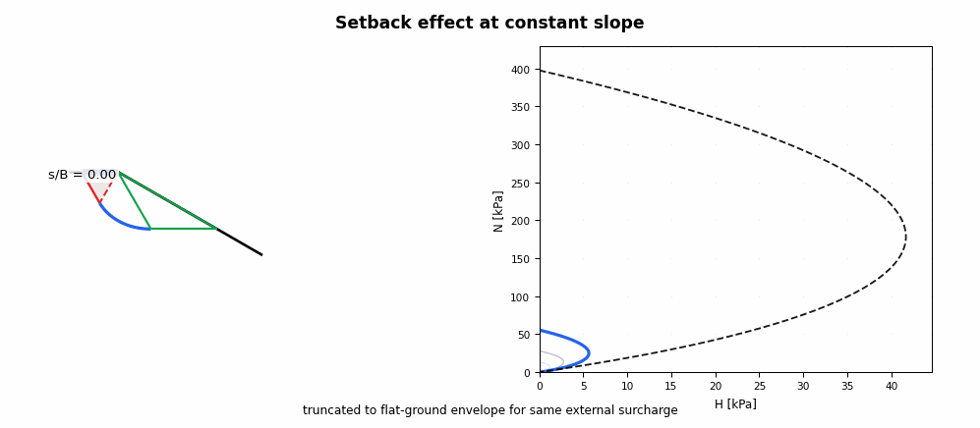
Figure 1. Drained failure mechanism and H-N envelope as setback increases. The slope angle is constant and the setback wedge unit weight is taken equal to the soil unit weight.
Near the slope crest, the failure mechanism is strongly influenced by the slope. As the setback increases, the influence of the slope decreases. Eventually, the mechanism approaches the flat-ground case.
For drained conditions, the method is expressed using the effective stress parameters c’, and φ’. The assumed mechanism consists of an active Rankine zone, a transition zone and a passive Rankine zone. The transition zone is a logarithmic spiral, as expected for a frictional bearing-capacity mechanism.
A useful way to write the drained formulation is to use the attraction term

A peculiarity of the drained case is that the no-influence setback distance is not only a geometric quantity. It depends on the foundation width, the friction angle and the mobilized roughness.
Another peculiarity is the contribution from unit weight. Near the crest, the passive side of the mechanism is restricted, and the 
The implementation may also include a setback wedge surcharge. In the demonstration above, the setback wedge unit weight is taken equal to the soil unit weight:

This surcharge can increase the calculated resistance. For design use, however, it is usually sensible to prevent the slope-adjacent capacity from exceeding the corresponding flat-ground capacity for the same surcharge condition.
Undrained case
For undrained conditions, the method is expressed using the undrained shear strength, c_u. The undrained case can be viewed as the limiting case of the drained mechanism when the friction angle is zero:

The logarithmic spiral transition zone then becomes a circular arc. The undrained mechanism is therefore geometrically simpler than the drained one.
The vertical bearing resistance can be written conceptually as

where 

A peculiarity of the undrained interaction problem is that the horizontal resistance is directly linked to the mobilized undrained strength:

Here, 


The undrained formulation does not contain a drained-type N_gamma contribution. Soil unit weight does not enter the undrained bearing-capacity expression in the same way as in the drained formulation. However, a setback wedge surcharge may still be included as an external stabilizing surcharge where appropriate.
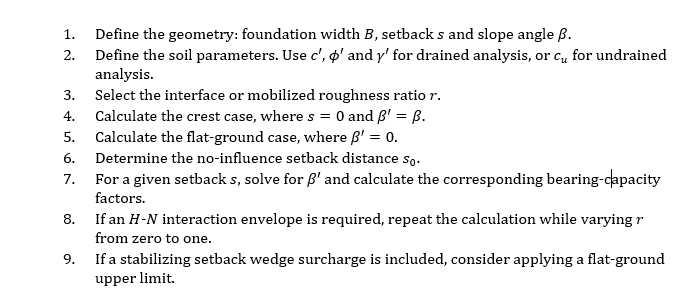
How to implement the mechanism-based method
A practical implementation can be organized as follows.
The optional flat-ground upper limit can be written as

This prevents the bearing capacity adjacent to the slope from exceeding the equivalent flat-ground value.
Linear interpolation simplification
A simpler approximation is to interpolate linearly between the crest case and the flat-ground case. This simplification was first mentioned in Døssland’s (1980).
The idea is direct. First calculate the bearing capacity at the slope crest. Then calculate the bearing capacity for flat terrain. Finally, interpolate between these two values using the setback distance.
Let the bearing capacity at the slope crest be q0, the flat-ground bearing capacity be 
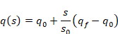
for

For setback distances beyond the no-influence distance,

for

The same idea can be applied to 


This linear-interpolation version is attractive because it is easy to implement and explain. It is best treated as a preliminary design check or a sensitivity tool, not as a substitute for a full mechanism-based or numerical analysis.
Limitations of the method
The method is simplified and should be used with engineering judgement. It is based on an assumed failure mechanism and is most naturally suited to strip foundations under plane-strain conditions.
It does not explicitly model progressive failure, strain softening, complex layering, anisotropy, groundwater effects, cyclic degradation, or three-dimensional foundation shape effects unless these are introduced separately through engineering approximations.
The method checks bearing capacity adjacent to a slope. It does not by itself prove that the slope is globally stable. This distinction is important: a foundation may have adequate local bearing capacity while the slope as a whole may still be unsafe.
The method is also sensitive to the selected soil parameters. In drained analysis, the friction angle and effective unit weight strongly affect the result. In undrained analysis, the selected undrained shear strength profile is critical.
Always check slope stability
A bearing-capacity check adjacent to a slope should be accompanied by a slope-stability check. The local bearing-capacity mechanism and the global slope-failure mechanism are not necessarily the same.
The engineer should check whether the slope is stable before and after foundation loading. This is especially important for clay slopes, high slopes, slopes with weak layers, slopes affected by groundwater and slopes close to excavations.
If the slope stability factor of safety is low, the bearing-capacity result may not govern the design. The controlling failure mode may instead be a global or compound slope failure.
Advanced methods
For important projects, difficult ground conditions or marginal stability cases, more advanced methods should be considered. These include:
- limit equilibrium slope-stability analysis;
- finite-element analysis with strength reduction;
- finite-difference analysis;
- upper-bound and lower-bound limit analysis;
- finite-element limit analysis;
- numerical modelling with staged excavation and construction;
- coupled consolidation analysis for soft clays;
- probabilistic analysis where spatial variability of strength is important.
These methods can capture effects that are outside the simplified formulation, such as nonhomogeneous soil, groundwater, staged loading, deformation compatibility and global failure mechanisms.
Closing remarks
The bearing capacity of shallow foundations adjacent to slopes is controlled by both soil strength and geometry. The setback distance from the crest is especially important.
The method I proposed provides a simple way to account for this effect. At its most basic level, the bearing capacity can be interpolated linearly between the crest case and the flat-ground case. At a more detailed level, the method uses a changing mechanism governed by the modified slope angle 
For drained conditions, the method gives a frictional mechanism with a logarithmic spiral transition zone. For undrained conditions, the same framework reduces to a circular-arc mechanism. Both cases can be used to estimate bearing capacity and to generate 

The method is deliberately simple, visual and practical. Its purpose is to help engineers check shallow foundations adjacent to slopes while still recognizing when a full slope-stability or numerical analysis is required.
References
Tsegaye, A. B. (2019). Bearing capacity of shallow foundations that are situated at a varying distance from slopes. XVII European Conference on Soil Mechanics and Geotechnical Engineering.
Døssland, T. (1980). Forankring av støttekonstruksjo-ner med horisontale friksjonselement. NorgesTeknsike Høgskole Universitet.
Meyerhof, G. G. (1957). The ultimate bearing capacity of foundations on slopes. Proceedings of the 4th International Conference on Soil Mechanics and Foundation Engineering.

